The Technology
Deployment Apparatus
The deployment apparatus consists of three main components:
- Air duct with venturi and dry air inlet
- Hopper
- Gate valve with actuator
The Air Duct with Venturi and Dry Air Inlet
The air duct is located below the vehicle headlights in front of its front wheels. Its forward end has a two inch diameter opening in the front bumper. It extends horizontally back toward the front tire then turns 90 degrees down in a sweeping elbow before its discharge end which aims down toward the road just in front of the front wheels. An opening at the top of the sweeping elbow receives the flow of tractive medium from a hopper above.
As the vehicle moves forward, slip stream air enters and flows through the air duct at about the same speed as the road speed of the vehicle. Thus, as the tractive medium units fall into and are entrained in this diverted air stream, they are accelerated down toward the road at nearly the same speed as the vehicle’s road speed. The end result of this arrangement is that the tractive medium is always delivered to the road just in front of the front tires without any moving parts (except the gate valve below the hopper) at any normal highway speed
Because this air duct will receive slip stream air entrained with rain water it is necessary to prevent that moisture’s entry into the hopper and gate valve assembly. A venturi is constructed just forward of the opening connecting the sweeping elbow to the hopper above. This sets up a low-pressure area at that hopper opening. A small connection from the lower hopper plenum space connects to a nearby dry air source with a goose neck at its end. Thus, as the slip stream air moves back through the air duct the venturi sets up a low pressure at the opening to the hopper above. This low pressure pulls dry air from its nearby source though the gooseneck and into the lower plenum space of the hopper where it washes across the gate valve before being pulled down into the air duct opening. Any time the vehicle is moving forward this dry air is sweeping across the mechanical plenum space guaranteeing it is kept dry and functional.
The Hopper
Located just above the opening in the air duct elbow, the small hopper contains the JaxBites™
A fill tube with cap extends up to a convenient location under the engine hood. It is easily filled by simply pouring additional JaxBites in as needed.
The Gate Valve Assembly
The gate valve restrains the JaxBites in the hopper until a deployment event. At that time, a rotating actuator, taking its directions from the electronic controller, rotates and opens the valve to allow the JaxBites to fall by gravity into the air duct. The rate of JaxBites flow must be controlled to match the road speed and conditions so the gate valve opens and closes in a fluttering sequence that meters the flow as needed. This gate valve/rotary actuator is the only moving part of the Tracker.
A brush arrangement above the gate valve allows for the free movement of the valve while restraining the contents of the hopper.
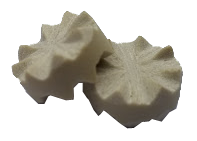
The JaxBites™
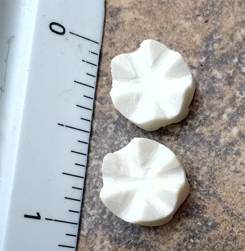
The JaxBites serves as the all-important third element between tire and road, to greatly increase friction forces only when needed and yet always when needed. Its vertical teeth ''bite'' into both the tire and the road surface.
Its overall shape is that of a disc. As a result, when these units land on the road surface their stable position is flat just as a penny lies flat on a table rather than on its edge. In this position the multiple double pointed pins around this disc’s perimeter engage with the tire above and the road surface below.
The diameter of the disc serves to resist the torque on these units as the wheel is braking. This prevents the ceramic units from tumbling under the tire during a braking or turning panic event.
The high-tech ceramic material has a compressive strength of 80,000 psi. Thus, the unit’s points withstand the stresses of being sandwiched between a tire and concrete road very well during use, yet will eventually degrade to an environmentally benign dust under continuous traffic.